
DIY Level 2 EV Charger Build
Let’s start off by correcting a popular misconception - a level 2 “EV Charger” does not actually perform the function of charging your car’s battery pack. Instead it simply advertises that maximum AC current it can supply and engages a contactor/relay when the car is ready. The actual charging circuitry resides within the car. The correct term for these home chargers is Electric Vehicle Supply Equipment (EVSE). It’s only job is to deliver power in a safe manner.
My initial plan when I purchased my Nissan LEAF was to buy an EVSE on Amazon and have an electrician install it for me. Looking at the features of various devices, I was a bit irritated at the “smart features” which required a WiFi connection and an app or browser to configure. I assumed a simple home charger would be a passive device what would just work when plugged-in. No high-tech complications required. In fact, my car came with such a device, but it only charges at 1kW which is too slow if I intend to drive every day.
Doing some more research, I learnt how the J1772 connector actually functions. Understanding it isn’t difficult if you are electrically-savvy. You can find the details here:
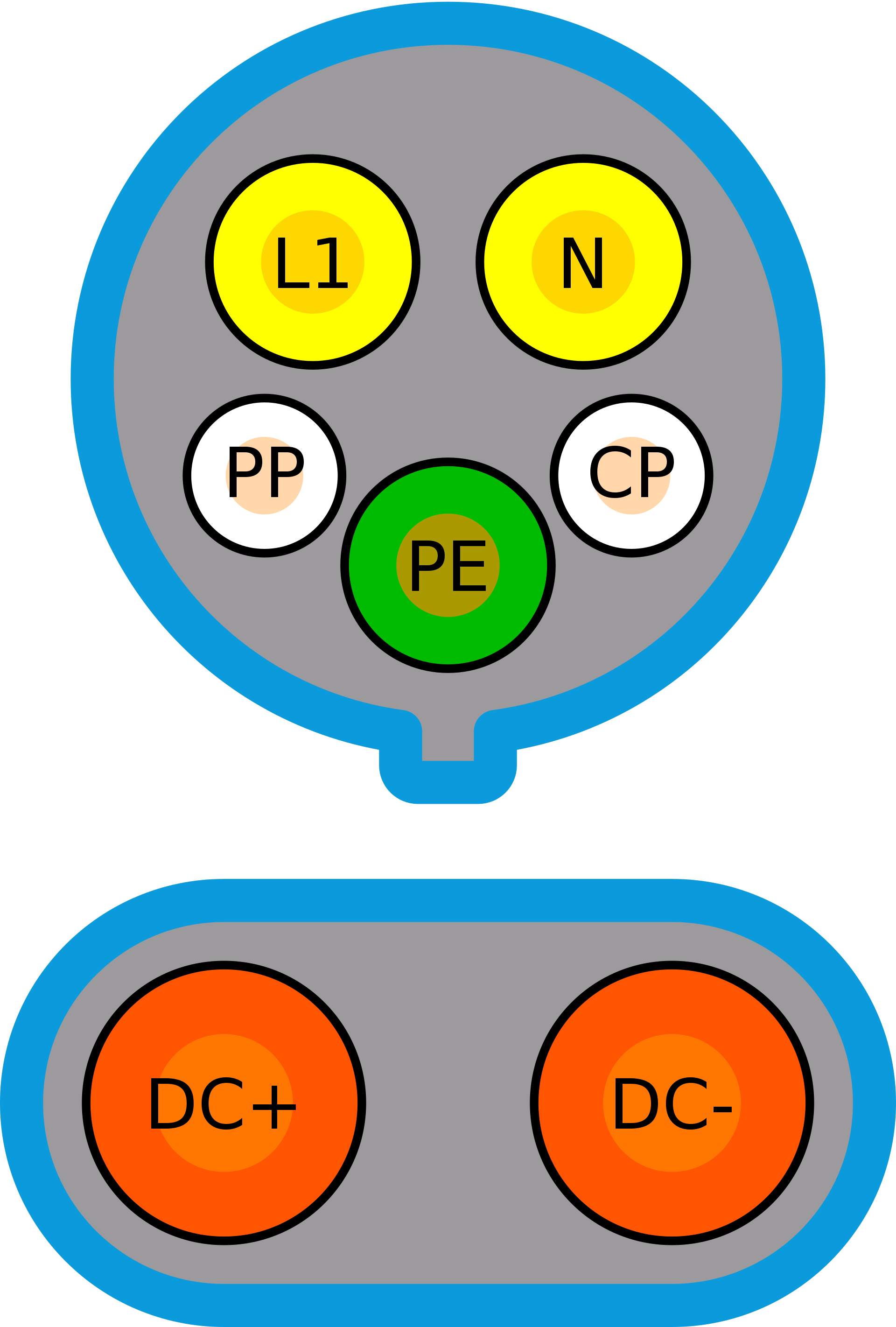
Only the top portion of the connector is used for Level 2 charging. The DC+ and DC- pins are for fast charging at 50kW or more and are part of the CCS standard.
On the J1772 connector, three out of the 5 pins simply deliver 240VAC (L1, N + PE) to the car. The additional two pins: Proximity Pilot (PP) and Control Pilot (CP) are involved in letting the car know when the cable is connected and how much power the EVSE can deliver.
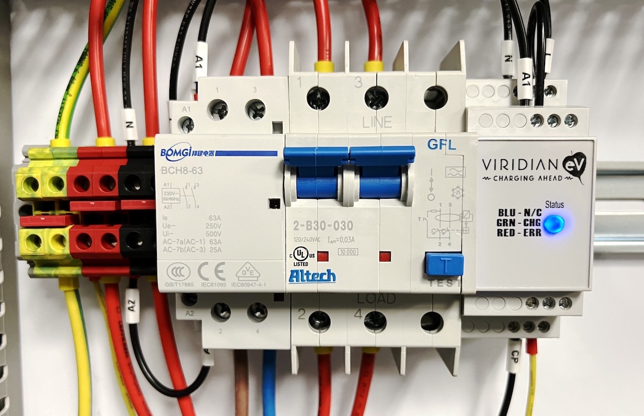
Delivering power to the L1, N and PE pins doesn’t require any sophisticated electronics. All you need is a circuit-breaker (GFCI preferably) and a contactor. The circuit breaker prevents the car from drawing too much current and also protects against short circuits. The PP pin functionality is built into the J1772 handle. The last piece of the puzzle is the CP pin. This pin provides a PWM signal to the car indicating how many amps the EVSE can deliver. For this, I used a ready-made device from Viridian called EVSE Protocol Controller. Its job is to communicate with the car to set a charging current limit. Once the car is ready (it informs its status by changing voltage on the CP pin), it turns on the contactor so that current can start flowing.
As you can see from the diagram below, the system is fairly simple in theory (this schematic is for communicating the general idea only and is missing some connections).
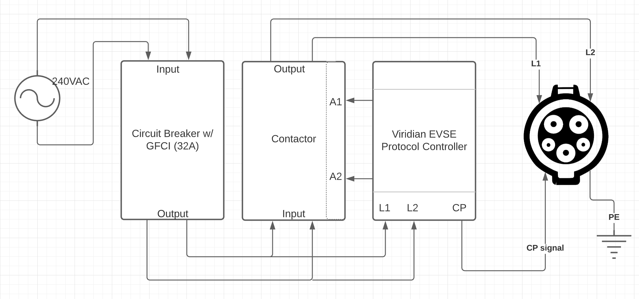
There are some areas that need to be paid special attention:
The system is designed to deliver a maximum of 32 amps. So the use of adequate gauge wire to handle the load is essential. Otherwise, you could overheat the wires and start a fire. I ended up using 10AWG (6 mm2) wires in my control panel and 8AWG (10 mm2) wires to bring power to the panel itself. Use a circuit breaker with GFCI protection. In most countries, you would have a 240V live wire and a Neutral, however in the USA, you have two live wires. So make sure your breaker is designed to work in a split-phase system which breaks contact on both wires. Make sure your contacts are solid. Use ferrules any time you have stranded wires. Use certified products only (UL listed or CE) I happened to have a control panel already installed in my garage. It is used in my other home automation projects. However, you could buy an enclosure for a project such as this and mount the components on a DIN rail.
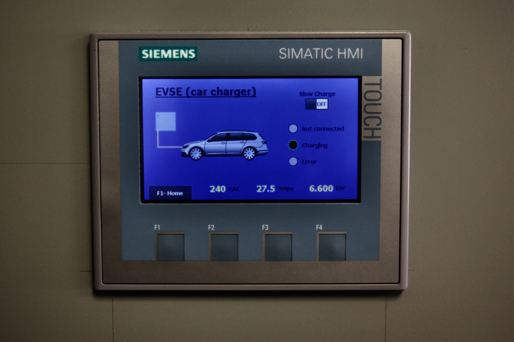
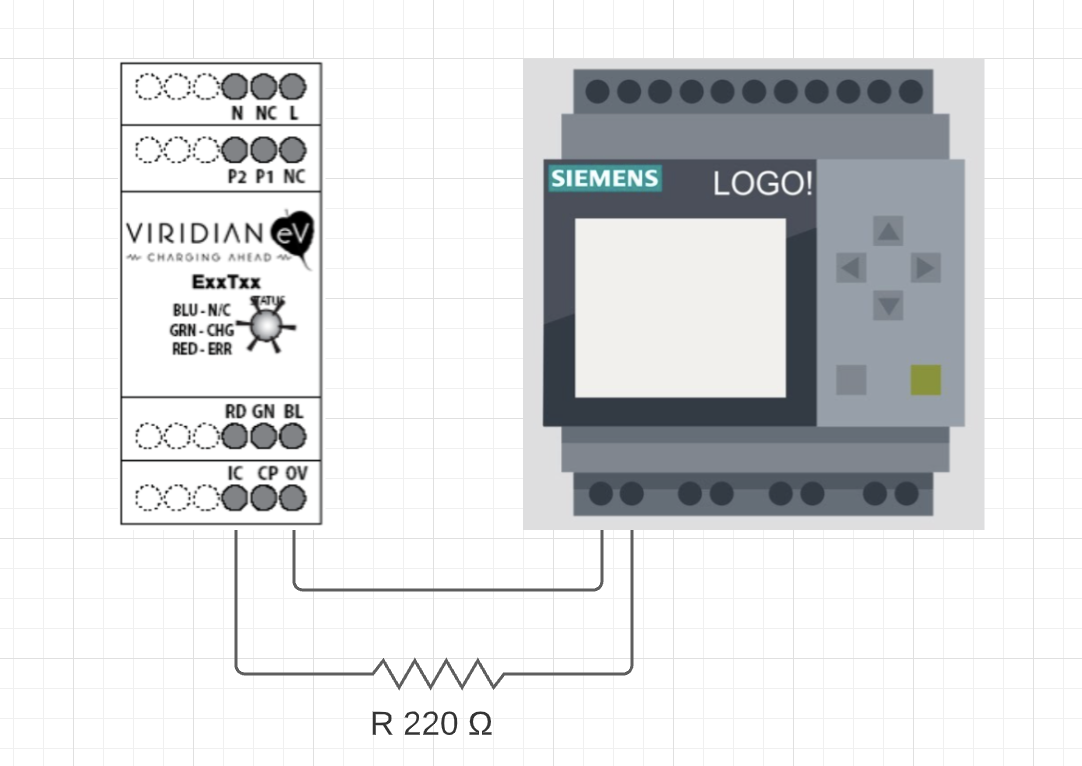
In the video above, you see that I am able to control the charge current also. I have two settings – a slow charge (1.8kW) and normal charge at (7.7kW). This is accomplished by connecting a 220Ω resister between the 0V and IC pins. Since I have a PLC nearby, I used a relay on it to connect and disconnect the resistor as needed.
The rest of the project involved programming the existing PLC and HMI in the control panel to display the stats on the screen. There is also a AC current transducer that is used to collect the energy delivered information.